 |
Version 8.9.0
|

|
|
Version 8.9.0
|
|
| Function | Easy API | Expert API |
|---|---|---|
| Programming Style | Simple Function Calls | Object Orientated |
| Programming Language | C, C++, C#, Matlab, Labview, Python and every other with C-Library Support | C++ |
| Thermal Image | ✅ | ✅ |
| Palette Image | ✅ | ✅ |
| Change Palette Color | ✅ | ✅ |
| Change Palette Scale | ✅ | ✅ |
| Change Palette Temperature Range | ✅(since v8.0) | ✅ |
| Set Focus Motor Position | ✅ | ✅ |
| High Precision Mode (PI450) | ✅ | ✅ |
| Extended Temperatur Range | ✅ | ✅ |
| RAW Data Recording for PIX-Connect | ❌ | ✅ |
| Access to visible frame (PI230) | ❌ | ✅ |
| Multiple Cameras | ✅(since v8.0) | ✅ |
| PIF I/O Support | ❌ | ✅ |
| Detect Connection Loss | ❌ | ✅ |
| Flagcontrol during Runtime | ✅(since v8.0) | ✅ |
| Create Optris Tiff Files | ❌ | ✅ |
| Temperature referencing with external probe (BR 20AR) | ❌ | ✅ |
The PI and XI imagers provide different video formats. Depending on the camera model, the user can choose different resolutions and frame rates respectively by specifying the so called "videoFormatIndex" (see structure IRDeviceParams and section Generating configuration files). For instance, the parameter chooses specific formats for the following devices:
| XI 80 (FW 3016..3199) | XI 400 (FW 3400..3599) | |||
|---|---|---|---|---|
| videoFormatIndex | Raw format | Image format | Raw format | Image format |
| 0 | 80x82@50Hz | 80x80@50Hz | 382x290@27Hz | 382x288@27Hz |
| 1 | 80x82@8.33Hz | 80x80@8.33 | 382x288@80Hz | 382x288@80Hz |
| XI 410 USB (FW 3800..3999) | XI 410 Ethernet (FW 3800..3999) | |||
|---|---|---|---|---|
| videoFormatIndex | Raw format | Image format | Raw format | Image format |
| 0 | 384x242@4.1Hz | 384x240@4.1Hz | 384x242@25Hz | 384x240@25Hz |
| 1 | 80x82@8.33Hz | 80x80@8.33 | 382x288@80Hz | 382x288@80Hz |
| XI 410MT USB (FW 3800..3999) | XI 410MT Ethernet (FW 3800..3999) | |||
|---|---|---|---|---|
| videoFormatIndex | Raw format | Image format | Raw format | Image format |
| 0 | 384x242@4.1Hz | 384x240@4.1Hz | 384x242@25Hz | 384x240@25Hz |
| 1 | 80x82@8.33Hz | 80x80@8.33 | 382x288@80Hz | 382x288@80Hz |
| XI 1M USB (FW 4000..4199) | XI 1M Ethernet (FW 4000..4199) | |||
|---|---|---|---|---|
| videoFormatIndex | Raw format | Image format | Raw format | Image format |
| 0 | 132x102@20Hz | 132x100@20Hz | 396x302@20Hz | 396x300@20Hz |
| PI 160 (FW 2026..2199) | PI 400/450 (FW 2438..2599) | PI 640 (FW 2600..2799) | ||||
|---|---|---|---|---|---|---|
| videoFormatIndex | Raw format | Image format | Raw format | Image format | Raw format | Image format |
| 0 | 160x122@120Hz | 160x120@120Hz | 382x290@27Hz | 382x288@27Hz | 642x480@32Hz | 640x480@32Hz |
| 1 | - | - | 384x288@80Hz | 382x288@80Hz | 642x120@125Hz | 640x120@125Hz |
For a PI 1M device, the format maps as follows. Important notice: The chosen temperature range is related to these image formats:
| PI 1M | |||||
|---|---|---|---|---|---|
| videoFormatIndex | FW | Raw format | Image format | Min. Temp | Max. Temp |
| 0 | 2800..2818 | 385x289@27Hz | 382x288@27Hz | 450 | 1800 |
| 2818..2999 | 382x290@27Hz | 382x288@27Hz | 450 | 1800 | |
| 1 | 2800..2999 | 384x288@80Hz | 382x288@80Hz | 500 | 1800 |
| 2 | 2800..2999 | 766x480@32Hz | 764x480@32Hz | 500 | 1800 |
| 3 | 2800..2817 | 73x224@250Hz | 72x56@1000Hz | 600 | 1800 |
| 2818..2819 | 74x224@250Hz | 72x56@1000Hz | 600 | 1800 | |
| 2820..2999 | 74x224@250Hz | 72x56@1000Hz | 600 | 1800 | |
| 4 | 2800..2999 | 768x32@250Hz | 764x8@1000Hz | 600 | 1800 |
For a PI 05M device, the format maps as follows. Important notice: The chosen temperature range is related to these image formats:
| PI 05M | ||||
|---|---|---|---|---|
| videoFormatIndex | Raw format | Image format | Min. Temp | Max. Temp |
| 0 | 385x289@27Hz | 382x288@27Hz | 900 | 2450 |
| 1 | 384x288@80Hz | 382x288@80Hz | 950 | 2450 |
| 2 | 766x480@32Hz | 764x480@32Hz | 950 | 2450 |
| 3 | 73x224@250Hz | 72x56@1000Hz | 1100 | 2450 |
| 4 | 768x32@250Hz | 764x8@1000Hz | 1100 | 2450 |
For a PI 08M device, the format maps as follows. Important notice: The chosen temperature range is related to these image formats:
| PI 08M | ||||
|---|---|---|---|---|
| videoFormatIndex | Raw format | Image format | Min. Temp | Max. Temp |
| 0 | 385x289@27Hz | 382x288@27Hz | 575 | 1900 |
| 1 | 384x288@80Hz | 382x288@80Hz | 625 | 1900 |
| 2 | 766x480@32Hz | 764x480@32Hz | 625 | 1900 |
| 3 | 73x224@250Hz | 72x56@1000Hz | 750 | 1900 |
| 4 | 768x32@250Hz | 764x8@1000Hz | 750 | 1900 |
The user should check available video formats with a standard camera application, e.g., guvcview and valid temperature parameters by examining the provide calibration files.
<formatspath>/opt/piimager</formatspath> <– The Folder contains the Formats.def file (raw camera formats)
<imager xmlns:xsi="http://www.w3.org/2001/XMLSchema-instance" xmlns:xsd="http://www.w3.org/2001/XMLSchema">
<serial>YOURSERIAL</serial> <– Provide serial number, if you attach more than one camera
<videoformatindex>0</videoformatindex> <– Index of the used video format(USB enpoint) – Link to the Video Formats
<calipath>/usr/share/libirimager/cali</calipath> <– Contains the configuration file (.XML)
<fov>33</fov> <– Field of View
<temperature> <– Temperature range the camera is supposed to locate
<min>-20</min>
<max>100</max>
</temperature>
<optics_text></optics_text>
<framerate>32.0</framerate> <– Framerate must be less or equal to the Camera framerate
<outputmode>2</outputmode> <– 1=Energy, 2=Temperature
<bispectral>0</bispectral> <– 0=only thermal sensor, 1=bispectral technology (only PI200/PI230)
<autoflag>
<enable>1</enable>
<mininterval>15.0</mininterval>
<maxinterval>0.0</maxinterval>
</autoflag>
<tchipmode>0</tchipmode> <– 0=Floating (default), 1=Auto, 2=Fixed value -->
<tchipfixedvalue>40.0</tchipfixedvalue> <– Fixed value for tchipmode=2 -->
<focus>-1</focus>
<enable_extended_temp_range>0</enable_extended_temp_range> <– 0=Off, 1=On; Caution! Enables invalid extended temp range-->
<buffer_queue_size>5</buffer_queue_size> <– internal buffer queue size -->
<enable_high_precision>0</enable_high_precision> <– 0=Off, 1=On; Enables temperatures with more than 1 decimal places. Depends on used camera(IRImager::getTemprangeDecimal()).-->
<radial_distortion_correction>0</radial_distortion_correction>
<use_external_probe>0</use_external_probe> <– 0=Off, 1=On; Temperatures values of external probe BR20AR are accessible on PIFs first analog input in °C-->
</imager>
Typically, a DirectShow graph is used to acquire raw data. The user can employ an own implementation or use the library-contained IRDeviceDS class. After calling the blocking run method, the class instance will call a callback function/method frequently as soon as data is available. This data is to be passed to the process method of an IRImager instance. It uses itself the callback functions/methods onThermalData , onVisibleFrame and onFlagStateChange to pass converted data to the user. The following sequence diagram documents this typical usage.
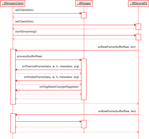
A C-style example is also available. The main difference is the usage of callback functions, instead of callback class methods.
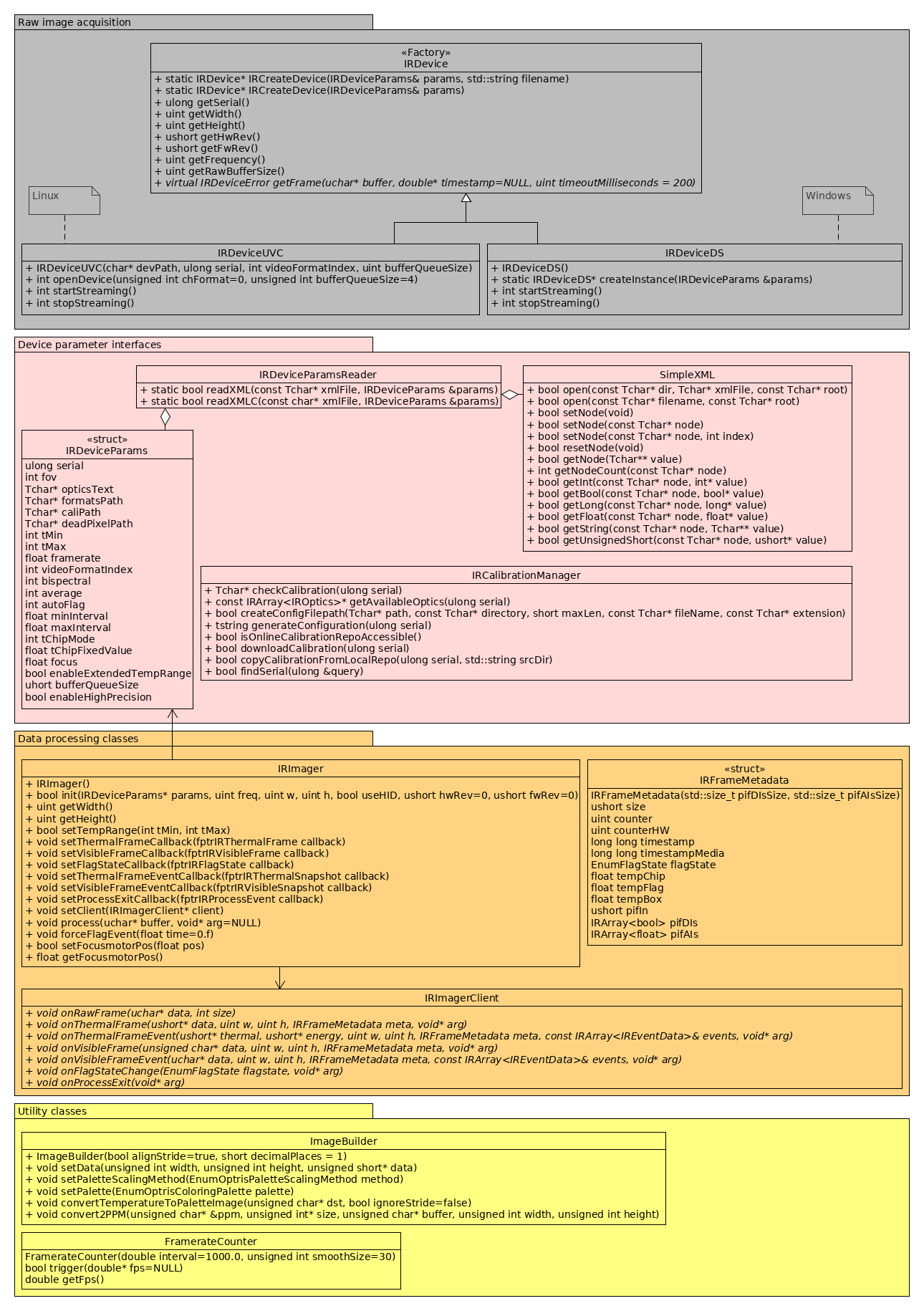
A class diagram of the most important library classes is depicted below.
It is recommended to keep the callback functions/methods lightweight in order to guarantee a high framerate of process method calls. Some of the provided examples show how to copy data in a queue within the callback functions. A worker thread is subsequently informed to do further processing
The callback methods are using an unsigned short data representation for temperatures. In order to get temperature values in floating point format, the following conversion needs to be applied:
void onThermalFrame(unsigned short* thermal, unsigned int w, unsigned int h, IRFrameMetadata meta, void* arg)
{
...
float t = (float)thermal[i] / 10.f - 100.f;
...
}
The Direct SDK supports the PIF of Optris imagers. See pif/IRPifExample.cpp for an example code.
In order to receive images at rising edge events of the PIF digital input, the user needs to register a callback function via the IRImager class instance:
void IRImager::setThermalFrameEventCallback(fptrIRThermalFrame callback)
for thermal images and
void IRImager::setVisibleFrameEventCallback(fptrIRVisibleFrame callback)
for RGB images of cameras supporting bispectral technology.
Alternatively, one can use the object oriented interface by deriving the class IRImagerClient . For more information see the provided examples.
The following code enables snapshot triggering:
 //Get initialized pif config

 IRPifConfig pifConfig = imager.getPifConfig();

 if(pifConfig.ChannelsDI.size() > 0)

 {

   pifConfig.ChannelsDI[0].Mode = IRChannelInputMode::SnapshotOnEdge; //Trigger only on edge

   pifConfig.ChannelsDI[0].IsLowActive = false; //Trigger on rising edge

 }

 //Set pif config for apply new configuration

 imager.setPifConfig(pifConfig);
The automatic flag control can be deactivated ( <autoflag> tag in the xml configuration file). Flag cycles can be triggered manually by the PIF input:
 //Get initialized pif config

 IRPifConfig pifConfig = imager.getPifConfig();

 if(pifConfig.ChannelsDI.size() > 0)

 {

   pifConfig.ChannelsDI[0].IsLowActive = true; //Invert, to close flag on true

   pifConfig.FlagOpenInputChannel = pifConfig.ChannelsDI[0]; //Set which channel controls flag

 }

 //Set pif config for apply new configuration

 imager.setPifConfig(pifConfig);
To improve the specified camera accuracy of the PI 450i T010 camera a reference source with a high emissivity and a stable and known temperature must be positioned in the scene proximate to the subject to be scanned. The BR 20AR Ambient referencing source is equipped with a temperature probe with +/- 0.1 °C accuracy.
To access the temperature values of the BR 20AR the configuration parameter <use_external_probe> must be set to 1. The temperature value will then be written to the first pif analog input channel in °C.
See "externalProbe/IRExternalProbe.cpp" on linux or "examples\\directshow\\irExternalProbe.cpp" on windows for an example code.
If high percision mode is activated (enable_high_precision=1 in config.xml), the data representation depends on the supported decimal places of the thermal camera. The supported decimal places can be retrieved by the evo::IRImager::getTemprangeDecimal() method of the IRImager.h.
void onThermalFrame(unsigned short* thermal, unsigned int w, unsigned int h, IRFrameMetadata meta, void* arg)
{
...
short decimalPlaces = _irImager.getTemprangeDecimal();
float divisor = std::pow(10, decimalPlaces);
float t = (float)thermal[i] / divisor - 100.f;
...
}
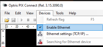
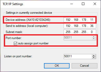
<device_api>5</device_api>
<ethernet_device>
<device_ip_address>192.168.0.11</device_ip_address>
<local_udp_port>50011</local_udp_port>
<check_udp_sender_ip>1</check_udp_sender_ip>
</ethernet_device>
Important:
A class diagram of the most important library classes is depicted below.
IRDeviceUVCr and IRDeviceDS are acquisition classes for raw data streams under Linux (UVC) and Windows (DS==DirectShow). IRDeviceParamsReader is a helper class and parses a configuration file in order to create an IRDeviceParams structure instance. This structure can also be instantiated and populated with parameters manually. SimpleXML is a lightweight XML parser and used by the IRDeviceParamsReader class internally. The user might also employ it for reading application specific XML files. IRCalibrationManager may be used to download or copy calibration files with the user's own program. Currently, there is no full support for the Windows operation system. IRImager is the main class and is used for processing raw data and controlling the PI imager device. IRImagerClient is an abstract class that enables object oriented interfacing of PI imagers. The library uses callback methods to inform the user of the availability of thermal or RGB data. IRImager either accepts pointers to C-style callback functions or a pointer to an inherited class instance of IRImagerClient. IRFrameMetadata is a meta data container delivered by the PI imager within its raw data stream. It contains timestamp and internal state parameters. ImageBuilder can be used to convert temperature data to a displayable format. FramerateCounter states a helper class for calculating the frame rate of a loop. In the examples it is used to calculate the loop rate of a grabbing thread and a display thread.It is recommended to keep the callback functions/methods lightweight in order to guarantee a high framerate of process method calls. Some of the provided examples show how to copy data in a queue within the callback functions. A worker thread is subsequently informed to do further processing. Please see the next two sections about example applications to start your development.